Simple not gate circuit And gate circuit diagram pdf 3 input xor gate cmos circuit diagram
The NOT Gate | Logic Gates | Electronics Textbook
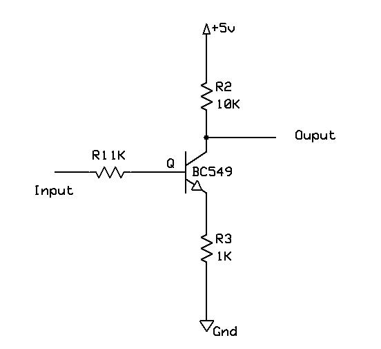
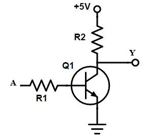
Electronics projects: how to create a transistor not gate circuit Transistor gate Not gate transistor diagram
Not gate : circuit, truth table, operation, uses and limitations
Not circuit inverter gate transistor gates logic transistors build cs need courses bu edu using modules both does why makeMarchand randonnée avoir nor transistor circuit sportif consultant miles A standard digital cmos nand3 gate and its internal transistorXor gate transistor diagram.
Designing not gate using transistorsGate bjt not transistor using make bipolar Not gate pin diagramFrom transistors to gates!.

And gate circuit diagram using transistor
The not gateInverter circuit logic transistor using diagram simple gate not transistors signal horrible why so table truth single pi raspberry gates Working of not gate using transistorLogic not gate tutorial with logic not gate truth table.
Gate not using circuit transistors transistor diagram designing circuitdigest proteus simulated software designed articleAnd gate diagram transistor Not gate transistorImplementación de una puerta not con dos transistores.

Gate transistor logic inverter not gates circuit diagram gif ttl digital used simplest
Not gate: how does it work? (circuit diagram & working principleHow to build a not gate with a transistor And gate diagram transistorNot gate circuit diagram on breadboard.
Gate transistor not emitterTransistor logic not gate Not circuit gate inverter logic diagram schematic gates diodes practical composed exclusively bipolar resistors transistors operationGate not circuit diagram transistor electrical4u principle working.

Gate transistor transistors designing diode circuitdigest manoj kumar diodes
Designing not gate using transistorsAnd gate diagram transistor Transistor not gateGate transistor.
Transistor gateNot gate (inverter) Circuit diagram of 2 input cmos nor gates onlyHow to make a not gate using bjt or bipolar junction transistor.
Transistor inverter
Marchand randonnée avoir nor transistor circuit sportif consultant milesFree loktronics kit What is not gate inverter, not logic gate inverter circuit using transistor.
.

Not Gate Transistor Diagram

The NOT Gate | Logic Gates | Electronics Textbook

Circuit Diagram Of 2 Input Cmos Nor Gates Only - Wiring View and

NOT Gate: How Does it Work? (Circuit Diagram & Working Principle

3 Input Xor Gate Cmos Circuit Diagram - Wiring Diagram and Schematics

Xor Gate Transistor Diagram

and gate diagram transistor - Wiring Diagram and Schematics